Table of Contents >> Show >> Hide
- What Is a Bubble LED Display?
- Why Build a 16×2 Bubble LED Display?
- The Display Module: Small, Smart, and Surprisingly Capable
- The Challenge: Too Many Pins, Not Enough Microcontroller
- Using 74HC595 Shift Registers to Save Pins
- Designing the PCB for a Clean 16×2 Layout
- Software: Treat the Display Like a Tiny Terminal
- Power and Heat: The Unromantic but Important Part
- Cleaning Vintage Bubble Displays Without Regret
- Common Problems and Practical Fixes
- Where a 16×2 Bubble LED Display Shines
- Hands-On Experience Notes: What Building One Teaches You
- Conclusion
- SEO Tags
There are display projects, and then there are display projects that look like they escaped from a 1970s calculator, put on a tiny red spacesuit, and demanded to be wired to a modern microcontroller. Chaining together a 16×2 bubble LED display is firmly in the second category. It is charming, slightly impractical, wonderfully nerdy, and exactly the kind of electronics build that reminds you why glowing red segments still have more personality than a dozen sterile LCD modules.
The idea is simple on the surface: take a collection of vintage four-character bubble LED modules, arrange them into two rows of sixteen characters, and control the whole display from a microcontroller using as few pins as possible. Underneath that simple goal sits a neat engineering puzzle involving smart alphanumeric displays, shared buses, shift registers, write-enable lines, power planning, socketed components, and one very important warning: do not casually bathe old clear plastic lenses in isopropyl alcohol unless you enjoy watching your parts develop a tragic spiderweb aesthetic.
This guide explores how a 16×2 bubble LED display can be chained together, why the HPDL-1414/DL1414-style display family is so fun to work with, and what practical lessons matter when turning a handful of tiny vintage displays into a usable serial display module.
What Is a Bubble LED Display?
A bubble LED display is a small LED display module with molded magnifying lenses over the characters. Those lenses give the display its “bubble” look and make tiny red LED characters appear larger and brighter. Before inexpensive LCDs became the default for calculators, watches, instruments, and test equipment, bubble LEDs were a clever way to squeeze readable digits into small spaces.
Many common bubble displays were numeric only, but the HPDL-1414 and related DL1414-style modules are more interesting because they are alphanumeric. Each module contains four characters, and each character is formed with multiple LED segments rather than a simple seven-segment digit. That means the display can show letters, numbers, punctuation, and symbols well enough for compact messages, status readouts, counters, clocks, debugging consoles, or retro sci-fi props that look like they belong on a spacecraft built by people with excellent taste in red plastic.
Why Build a 16×2 Bubble LED Display?
The classic 16×2 LCD module became popular because it is inexpensive, easy to control, and practical. A 16×2 bubble LED display is not the practical replacement you choose when you want low current, high contrast in daylight, or maximum efficiency. It is the display you choose because it looks fantastic. A red bubble LED array has depth, warmth, and texture. It looks alive in a way that flat displays often do not.
A 16×2 layout is also familiar. Two rows of sixteen characters are enough for menu labels, sensor readings, serial messages, short prompts, retro terminal text, clock and date displays, or compact embedded dashboards. By arranging eight four-character modules into two rows, the builder gets thirty-two total characters while preserving the iconic vintage look.
The Display Module: Small, Smart, and Surprisingly Capable
The heart of this type of project is the smart four-character alphanumeric LED module. The HPDL-1414 is commonly described as a four-character, sixteen-segment, red GaAsP display with a tiny character height of about 2.85 mm. The important word is “smart.” Unlike a raw LED matrix or bare segment display, these modules include onboard logic. Inside the package are memory, an ASCII decoder, multiplexing circuitry, and LED drivers.
That onboard intelligence makes the display far easier to control than a pile of individual LED segments. Instead of manually scanning every segment of every character, the microcontroller writes a character code into a selected character position. The module takes care of decoding and displaying it. In plain English: you tell the display, “Put the letter A in position 2,” and it does the tiny red magic.
For one module, the basic signals are straightforward. A seven-bit data bus carries the ASCII character value. Two address lines choose one of the four character positions. A write-enable signal tells the display when to store the data. Once the character is written, the onboard logic keeps it visible until you overwrite it. That makes the display feel more like writing to memory than driving LEDs directly.
The Challenge: Too Many Pins, Not Enough Microcontroller
One smart display is easy. Eight smart displays are where the fun begins. A 16×2 display needs eight four-character modules. If each module were controlled independently, the pin count would quickly become ridiculous. Seven data pins, two address pins, and a write-enable pin per display would consume far more microcontroller I/O than most small projects can spare.
The elegant solution is to share what can be shared. All eight displays can use the same seven data lines because only one module needs to be written at a time. The two address lines can also be shared because the selected character position means the same thing on every module. That gives a shared nine-line bus: seven data lines plus two address lines.
The only signal that must be unique for each module is write enable. Each display needs its own write-enable line so the controller can decide which four-character module receives the new character. With eight displays, that means eight individual write-enable lines. Add those to the nine shared bus lines, and the entire 16×2 display can be controlled with seventeen output signals.
Seventeen outputs are still more than many microcontroller projects want to sacrifice, but this is where shift registers enter wearing tiny capes.
Using 74HC595 Shift Registers to Save Pins
The 74HC595 is an eight-bit serial-in, parallel-out shift register with output latches. In project terms, it lets a microcontroller send data serially using just a few control lines, then present that data as multiple parallel outputs. One 74HC595 gives eight outputs. Three chained together give twenty-four outputs.
That is perfect for this display. Three 74HC595 chips provide enough outputs for the seven data lines, two address lines, eight write-enable lines, and several spare outputs. The microcontroller only needs a data line, a clock line, and a latch line. If desired, an output-enable line can be added for blanking or brightness control. With SPI hardware, the whole thing can be updated quickly and cleanly.
How the Chaining Works
In a chained setup, the serial output of one 74HC595 feeds the serial input of the next. The microcontroller shifts out three bytes, filling all twenty-four internal bits across the three chips. Then it toggles the latch line, and the new output states appear all at once. This avoids ugly half-updated signals and keeps the display writing sequence predictable.
To write a character, the software prepares a 24-bit pattern. Part of that pattern sets the seven-bit ASCII value. Another part sets the two-bit character address. One write-enable output is then pulsed for the target display module. The latch updates the shift register outputs, the display captures the character, and the software moves on to the next character.
The clever part is that the physical display looks like a 32-character screen, but electrically it behaves like a set of memory locations. The code maps row and column positions to a module number and a character address. For example, column 0 through 3 might belong to the first module, column 4 through 7 to the second, and so on. The second row repeats the pattern with four additional modules.
Designing the PCB for a Clean 16×2 Layout
A breadboard can prove the concept, but a 16×2 bubble LED display deserves a proper PCB. The modules have many pins, and the wiring can become messy very quickly. A PCB keeps the shared data and address buses tidy, routes the write-enable lines cleanly, and makes the finished display feel like a real module rather than a wire nest auditioning for a horror movie.
Socketing the display modules is strongly recommended. Many HPDL-1414 and DL1414-style parts are old, obsolete, or bought as surplus. Some may have bent pins, weak characters, cracked lenses, or unknown history. Sockets make it possible to test, replace, or rearrange modules without desoldering fragile parts. They also help protect your investment if the price of vintage displays suddenly decides to behave like a collectible sneaker market.
Good PCB layout should include local decoupling capacitors near the shift registers and display power rails. LED displays can draw noticeable current, especially when many segments are lit. A practical 16×2 array may draw several hundred milliamps, and worst-case conditions can push the power requirement higher. Use a stable 5 V supply, wide enough power traces, and a common ground layout that does not rely on one heroic skinny trace doing all the work.
Software: Treat the Display Like a Tiny Terminal
The best software abstraction is to treat the display as a two-line text buffer. Instead of forcing the main program to think about chip numbers and address pins, create functions such as clearDisplay(), setCursor(row, col), and printText(). Internally, the driver can translate each character into the proper display module and character position.
A typical write process looks like this:
- Convert the desired character into a seven-bit ASCII value.
- Calculate which four-character display module contains the target column.
- Calculate which of the four character addresses should be written.
- Shift out the data, address, and write-enable pattern through the 74HC595 chain.
- Latch the outputs and strobe the correct write-enable line.
- Repeat until the full message is written.
This structure also makes it easier to add scrolling text, custom startup animations, blinking cursors, status icons, or serial input. The display may look vintage, but the software can be as friendly as any modern LCD library.
Power and Heat: The Unromantic but Important Part
Bubble LED displays are beautiful, but they are not sipping power like a modern low-power LCD. They are LEDs, and there are many of them. A full 16×2 array can draw enough current that power planning becomes part of the design, not an afterthought. If your display flickers, resets the microcontroller, or dims when many characters are lit, suspect the power supply before blaming the poor code.
Use a power source with enough current headroom. Add decoupling capacitors near the display modules and logic chips. Keep power and ground paths short and sturdy. If the microcontroller is powered from USB but the display is powered from a separate 5 V supply, connect the grounds together. Otherwise the logic signals have no shared reference, and the display may behave like it has been possessed by a very small red ghost.
Cleaning Vintage Bubble Displays Without Regret
One of the most useful lessons from real-world builds is that old clear display lenses can be fragile. Many bubble lenses are made from plastic that may react badly to common solvents. Isopropyl alcohol is often safe for cleaning circuit boards, but it can cause crazing, cracking, or clouding in certain acrylic-like plastics, especially when the parts are old and stressed.
For vintage displays, start gently. Use dry air, a soft brush, or a microfiber cloth. If more cleaning is needed, try a tiny amount of mild soapy water on a cotton swab, and test in an inconspicuous area first. Avoid soaking the display. Avoid aggressive solvents. Avoid assuming that “electronics cleaner” means “safe for every plastic lens ever molded during the Carter administration.”
Common Problems and Practical Fixes
Characters Appear in the Wrong Position
If characters land in the wrong slot, check the two address lines in both hardware and software. Swapped address pins can often be corrected in code, but it is better to catch the issue before ordering boards.
Only One Module Updates
This usually points to write-enable routing. Confirm that each module has its own write-enable line and that the software pulses the correct one.
The Display Flickers or Resets
Look at the power supply, ground routing, and decoupling. LED arrays can pull more current than expected when many segments are active.
Nothing Displays
Check orientation, supply voltage, output-enable states on the shift registers, latch timing, and whether the display expects active-high or active-low control signals. Also verify that the ASCII range being sent is supported by the module.
Where a 16×2 Bubble LED Display Shines
This kind of display is ideal for retrocomputing projects, custom clocks, audio gear, bench instruments, synth modules, cyberdeck dashboards, serial monitors, badge projects, and art installations. It is especially effective when the display is part of the visual identity of the project rather than just a utility readout.
A bubble LED display does not whisper information. It performs it. A temperature reading becomes a tiny red announcement. A clock becomes a glowing conversation piece. A serial debug display suddenly looks like it belongs in a secret lab where every switch has a satisfying click.
Hands-On Experience Notes: What Building One Teaches You
Working with a chained 16×2 bubble LED display feels different from assembling a modern plug-and-play module. A typical LCD or OLED display gives you a tidy interface and politely hides the messy details. A vintage bubble LED array invites you behind the curtain and says, “Here are the buses, here are the latches, here are the timing rules, and yes, you will now care deeply about which bit goes where.” That is part of the fun.
The first experience that stands out is the importance of planning the signal map before touching the PCB layout. On paper, seventeen outputs sound manageable. In routing, they become a puzzle. The seven data lines want to travel together. The two address lines should be consistent across every module. The write-enable lines need to reach their own displays without crossing everything like spaghetti at a family reunion. Labeling nets clearly and creating a small table for output assignments saves a lot of confusion later.
The second lesson is that sockets are not optional if you care about your sanity. Vintage displays may arrive with bent pins, oxidation, inconsistent brightness, or mysterious personality quirks. Being able to pull a module and test another one is a luxury for about five minutes, then it becomes a necessity. It also makes cleaning, inspection, and replacement much safer. Desoldering an old display from a finished board is nobody’s idea of a relaxing evening.
The third lesson is that software should be written as if future-you is tired. Do not scatter raw bit patterns all over the program. Create named constants for data bits, address bits, latch control, and write-enable positions. Build helper functions. Keep a display buffer. Make the code read like a story: place character, select module, pulse write enable, update buffer. When something goes wrong, clean structure turns debugging from archaeology into simple detective work.
The fourth lesson is about power. On the bench, it is easy to test one module and assume the full array will behave the same. It will not. Once thirty-two characters start glowing, current draw rises, voltage drops become real, and weak USB ports reveal their lack of ambition. A dedicated 5 V supply with comfortable headroom makes the display more stable and keeps the microcontroller from resetting at dramatic moments.
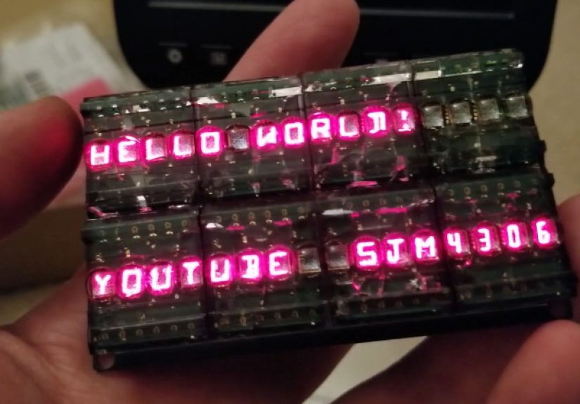
The fifth lesson is emotional: the first full message is ridiculously satisfying. Seeing “HELLO WORLD” appear across a row of tiny red bubble characters feels better than it reasonably should. The display has a jewel-like look that modern modules rarely match. It is not the most efficient way to show text, but efficiency is not the only measure of a great project. Sometimes the best build is the one that makes you grin every time it powers on.
Conclusion
Chaining together a 16×2 bubble LED display is a smart blend of retro hardware and practical digital design. By using smart four-character alphanumeric displays, shared data and address buses, and chained 74HC595 shift registers, a microcontroller can control thirty-two glowing characters with only a handful of pins. The project teaches useful lessons about bus design, serial-to-parallel expansion, PCB layout, power budgeting, vintage component handling, and clean display-driver software.
It is not the cheapest or most power-efficient way to build a text display. That honor belongs to modern LCDs and OLEDs. But if the goal is charm, character, and the kind of red glow that makes a project look instantly more interesting, a chained 16×2 bubble LED display is hard to beat. It is a tiny marquee from the golden age of pocket calculators, reborn with SPI, shift registers, and just enough stubborn delight to make the work worthwhile.
SEO Tags
Note: This article is based on real component behavior, vintage alphanumeric LED display documentation, practical hardware project references, and common electronics design practices. Verify pinouts, timing, voltage, and current limits against the exact parts used before building or publishing a final schematic.