Table of Contents >> Show >> Hide
- What Was the 2025 One Hertz Challenge?
- Why the 555 Timer Still Matters
- The Signal From Above: GPS 1PPS
- How the GPS-Disciplined 555 Timer Worked
- What the Measurements Revealed
- Why This Project Is Brilliantly Ridiculous
- Lessons for Makers and Electronics Hobbyists
- Specific Example: What a DIY Builder Could Try
- Experience Section: Living With One Hertz on the Workbench
- Conclusion
A one-hertz signal sounds almost too simple to be interesting. One tick per second. That is the pace of a wall clock, a blinking LED, a microwave countdown, and approximately the rhythm your patience keeps when a firmware upload freezes at 99 percent. But the 2025 One Hertz Challenge proved that “once per second” can become a glorious rabbit hole of timing accuracy, analog weirdness, GPS discipline, and old-school electronics charm.
The project behind “2025 One Hertz Challenge: 555 Timer Gets A Signal From Above” is a perfect example. It takes the legendary 555 timer, a chip famous for blinking LEDs and teaching beginners the joy of capacitors, and asks it to behave like a serious precision timing instrument. The punchline? The 555 gets help from abovenot divine intervention, though a few electronics benches could use itbut from GPS satellites sending highly accurate timing information down to Earth.
At first glance, using GPS to discipline a 555 timer feels a bit like hiring a Formula 1 pit crew to tune a lawn mower. But that is exactly why the project is fascinating. It is not about practicality. It is about learning, measuring, pushing a humble circuit beyond its natural habitat, and discovering where the messy real world starts arguing with the tidy formulas in a textbook.
What Was the 2025 One Hertz Challenge?
The 2025 One Hertz Challenge was a Hackaday.io contest built around one deceptively simple rule: create a device where something happens once per second. That “something” could be precise, ridiculous, mechanical, digital, analog, elegant, or completely unhinged. The challenge welcomed projects that treated one hertz as a serious timekeeping problem as well as projects that treated it as an excuse to make a machine blink, clunk, flash, flip, or complain once per second.
The contest categories encouraged creativity. There were precision-minded entries for people who wanted lots of zeroes after the decimal point. There were absurd entries for makers who believe a simple LED should be replaced with a contraption that looks like it escaped from a museum basement. And there was a category with a wonderfully knowing name: “Could Have Used a 555.” In electronics culture, that phrase is practically a reflex. If something needs to blink, pulse, delay, or oscillate, someone in the room will inevitably say, “You could use a 555.”
That is what makes this GPS-disciplined 555 timer so entertaining. It did use a 555. But it did not merely drop the chip into a beginner astable circuit and call it a day. Instead, it used the 555 as the analog heart of a timing system that listens to GPS and adjusts itself to stay aligned with a one-pulse-per-second reference.
Why the 555 Timer Still Matters
The 555 timer has been around since the early 1970s, and it remains one of the most recognizable integrated circuits ever made. Designed by Hans Camenzind while working with Signetics, the chip became famous because it was cheap, flexible, forgiving, and useful in an absurd number of circuits. Need a delay? Use a 555. Need a tone generator? Use a 555. Need a blinking warning light on a homemade robot that looks vaguely judgmental? Yes, use a 555.
In astable mode, the 555 acts as a free-running oscillator. With two resistors and one capacitor, it repeatedly charges and discharges the capacitor between internal threshold levels. The output flips state as the capacitor voltage crosses those thresholds, creating a rectangular waveform. Choose the right resistor and capacitor values, and you can get close to one hertz: one cycle per second.
The Classic Astable 555 Recipe
A textbook astable 555 circuit is beautifully simple. The timing capacitor charges through two resistors and discharges through one of them. The approximate frequency depends on the resistor values and capacitance, usually described by the familiar timing equations used in 555 calculators and datasheets. For a casual LED blinker, “close enough” is usually close enough. If the LED flashes a little faster in a warm room or a little slower because your capacitor is not exactly its labeled value, nobody calls the timing police.
But when the goal is accurate one-hertz timing, the 555 starts sweating. Real resistors have tolerance. Real capacitors drift with temperature, age, leakage, and voltage. Breadboards add noise and parasitics. Power supplies are not perfectly quiet. Even the control-voltage pin, normally bypassed with a small capacitor to keep things stable, becomes a doorway into the timer’s internal threshold system. That doorway is exactly what this project uses.
The Signal From Above: GPS 1PPS
GPS is best known for navigation, but location is only half the story. The Global Positioning System depends on extremely accurate time. GPS satellites carry atomic clocks, and receivers use timing information from multiple satellites to calculate position. That same timing information can also be used for synchronization.
Many GPS modules provide a 1PPS output, short for “one pulse per second.” This pulse is not just a casual blink. Its edge is aligned to the beginning of a GPS second, often with accuracy measured in tens of nanoseconds under good conditions and with appropriate hardware. For a maker building a clock, a data logger, a network time server, or an oscillator experiment, 1PPS is a gift from orbit.
That is the “signal from above” in this challenge entry. The GPS receiver provides a precise reference beat. The 555 provides the analog oscillator. The project’s job is to make the 555 follow the GPS beat without cheating too much.
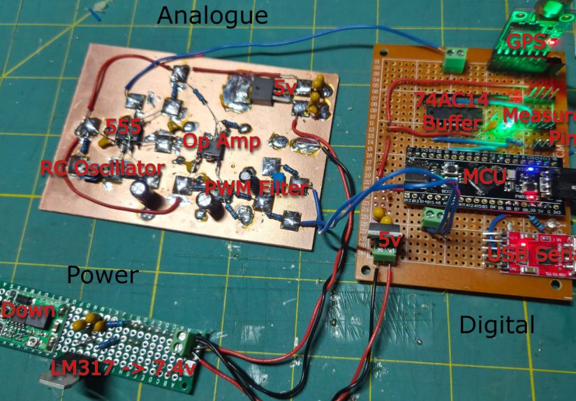
How the GPS-Disciplined 555 Timer Worked
The project used a normal astable 555 timer design as its foundation. That matters because the whole point was not to replace the 555 with a precision oscillator or let a microcontroller generate the pulse directly. The 555 had to remain the source of the one-pulse-per-second output. In other words, the chip still had to do the ticking.
The clever part was steering the 555 through its control-voltage pin. Inside the 555, a divider network sets reference levels for the comparators that determine when the timing capacitor has charged or discharged enough to flip the output. By applying a carefully controlled voltage to the control pin, the circuit can slightly shift those thresholds. Shift the thresholds, and the timing changes. Not dramatically, but enough to nudge the oscillator faster or slower.
The Microcontroller as Referee
A microcontroller watched both signals: the GPS 1PPS reference and the 555’s output pulse. It measured the timing difference between them, then adjusted the voltage applied to the 555 control pin. This created a feedback loop. When the 555 drifted away from GPS, the controller corrected it. When the phase difference grew, the controller nudged the oscillator so the 555 pulse could slide back into alignment.
The build used an STM32 microcontroller because accurate timing capture matters in a project like this. A basic microcontroller can blink an LED, but measuring small timing errors between pulses is a different game. Hardware timers, input capture, and stable measurement routines help turn a messy analog experiment into something that can be studied with real numbers instead of hopeful squinting at an oscilloscope.
PWM DAC, Filtering, and the Analog Reality Check
The steering voltage was generated using a PWM-based digital-to-analog approach. PWM is simple: rapidly switch a signal on and off, then filter it so the average becomes a controllable voltage. In theory, this is easy. In practice, the 555’s control voltage is sensitive, and tiny ripple or noise can wiggle the oscillator. If the PWM leaks through the filter, the circuit does not see a smooth steering voltage; it sees a tiny gremlin tapping on the timing thresholds.
This is where the project becomes more than “GPS plus 555 equals done.” The builder had to deal with layout, filtering, power-supply cleanliness, grounding, and physical construction. The analog and digital sections needed separation. The control voltage needed serious filtering. Breadboards, while wonderful for quick experiments and unexpected intermittent faults, were not ideal for low-noise precision timing. The final build moved toward lower-noise construction techniques, proving once again that analog circuits remember every shortcut you took.
What the Measurements Revealed
The most interesting part of the project was not that the 555 could be disciplined by GPS. It was how the results were measured and explained. The builder used Allan deviation, a standard way to evaluate oscillator stability over different averaging times. Allan deviation can sound intimidating, but the basic idea is friendly enough: it tells you how stable a frequency source is as you observe it over short, medium, and long intervals.
A free-running 555 RC oscillator can look decent over very short periods, then drift as temperature, component behavior, and noise sources take over. That creates the classic stability story of many oscillators: short-term noise matters at first, averaging helps for a while, and then long-term drift begins to dominate. GPS behaves differently because its long-term time reference is tied to satellite timing systems corrected and maintained for global use.
In the project’s measurements, the unlocked 555 showed the limits expected from an RC oscillator. It could produce a one-second pulse, but its stability was nowhere near that of GPS, an oven-controlled crystal oscillator, or a rubidium standard. Once disciplined, however, the 555 avoided some of the long-term drift that affected the free-running version. It became a better long-term follower of the GPS reference, even if it still remained hilariously uncompetitive compared with real precision timing hardware.
Why This Project Is Brilliantly Ridiculous
Let us be honest: if you already have GPS 1PPS, you do not need a 555 to generate a one-hertz signal. You could use the GPS pulse directly. You could feed it into a microcontroller, a counter, a clock distribution circuit, or a Raspberry Pi time server. Adding a 555 in the middle makes the system worse from a pure performance standpoint.
And that is precisely the charm.
The project is not trying to beat professional GPS-disciplined oscillators. It is trying to teach how GPSDO systems work by exaggerating the problem. A serious GPSDO combines a stable local oscillator with GPS long-term correction. The local oscillator handles short-term stability; GPS corrects long-term drift. In this build, the local oscillator is not a beautiful oven-controlled crystal. It is an RC 555 timer wearing a tiny lab coat and hoping nobody asks too many questions.
That mismatch makes the lessons clearer. You can see why short-term oscillator quality matters. You can see why feedback loops must be tuned carefully. You can see why phase lock and frequency lock are not the same thing. You can see how control voltage resolution, PWM ripple, and physical layout affect real measurements. The 555 becomes a teaching instrument, not because it is perfect, but because it is imperfect in visible, measurable, educational ways.
Lessons for Makers and Electronics Hobbyists
1. A Simple Circuit Can Become Deep Fast
A one-hertz 555 blinker is beginner-friendly. A GPS-disciplined one-hertz 555 is not. The difference is measurement. Once you ask “How accurate is it?” the project moves from blinking lights to metrology. Suddenly you care about microseconds, nanoseconds, oscillator noise, phase error, temperature drift, and whether your power supply is quietly ruining your day.
2. The Control Pin Is More Powerful Than It Looks
Many 555 circuits simply bypass the control-voltage pin and ignore it. This project makes that pin the steering wheel. By carefully adjusting the control voltage, the system changes the 555’s internal thresholds and therefore its oscillation timing. That is a wonderful reminder that “unused” pins often hide interesting possibilities.
3. Breadboards Are Great Until They Are Not
Breadboards are perfect for learning and prototyping. They are less perfect when you are chasing tiny timing errors in a mixed-signal circuit. Long jumper wires, shared rails, weak connections, and digital noise coupling into analog nodes can create strange behavior. If your circuit is doing something impossible, it may not be haunted. It may simply be breadboarded.
4. GPS Timing Is Powerful, But It Is Not Magic
GPS 1PPS is impressively accurate, but using it well requires care. Antenna placement, receiver quality, cable delay, signal conditions, and measurement equipment all matter. A GPS pulse can provide a beautiful reference, but the system built around it still has to respect physics.
5. “Badly” Can Still Be a Successful Result
Compared with professional GPS-disciplined oscillators, a disciplined 555 timer performs badly. But as an experiment, it succeeds beautifully. It locks. It measures. It teaches. It makes the invisible behavior of timing systems easier to understand. In engineering, the best project is not always the one that wins the spec sheet. Sometimes it is the one that explains the spec sheet while making you laugh.
Specific Example: What a DIY Builder Could Try
A simplified version of this idea would start with a standard 555 astable oscillator adjusted near one hertz. Use stable resistors, a decent capacitor, a clean supply, and a trimmer to get close. Feed the 555 output into a microcontroller timer input. Feed a GPS module’s 1PPS output into another timer input. Measure the time difference between rising edges. Then use filtered PWM or a real DAC to apply a small correction voltage to the 555 control pin.
The first goal should not be perfection. The first goal should be visibility. Can you measure the drift? Can you see the 555 run fast or slow? Can you apply a control voltage and watch the frequency shift? Can you filter PWM well enough that the oscillator is not being shaken by the correction signal itself? Each step teaches something useful.
The next goal is phase behavior. Frequency lock means the 555 ticks at the same average rate as GPS. Phase lock means its pulse edges line up with the GPS pulse edges. A clock can be frequency-correct but still offset in phase. That distinction matters in timing systems, and this project gives makers a hands-on way to experience it.
Experience Section: Living With One Hertz on the Workbench
Working on a one-hertz timing project changes your sense of time in a funny way. At first, one second feels slow. You press reset, wait for the next pulse, stare at the scope, and think, “This is relaxing.” Five minutes later, you realize every test takes forever because your circuit only reveals one new clue per second. Debugging at one hertz is like interviewing a very polite witness who answers exactly once per heartbeat.
The first practical experience is humility. A 555 circuit that looks correct on paper may blink happily on the bench but still be wildly unsuitable for precision timing. A capacitor marked 10 microfarads may not behave like an ideal 10 microfarad capacitor. A resistor may be within tolerance but still drift with heat. Touching the board, moving a wire, or breathing near a high-impedance analog node can produce tiny changes that matter when you are measuring timing error. Suddenly the circuit is not just electronic; it is environmental.
The second experience is respect for layout. In a casual LED blinker, power wiring is usually an afterthought. In a disciplined oscillator, power and ground become characters in the story. Digital switching noise from a microcontroller can sneak into the analog control voltage. PWM ripple can masquerade as a correction signal. A long ground path can turn into a shared complaint channel between parts of the circuit that should not be talking. Separating analog and digital sections, adding bypass capacitors, using a solid ground strategy, and filtering aggressively can make the difference between “interesting data” and “why does this graph look like it had coffee?”
The third experience is learning to trust measurements slowly. When a graph shows something strange, the circuit might be wrong. Or the code might be wrong. Or the measurement setup might be wrong. Or all three might have formed a tiny committee. A good builder checks assumptions one at a time: verify the GPS pulse, verify the timer capture, verify the PWM output, verify the filter response, verify the 555 reacts smoothly to control-voltage changes. Precision projects reward patience and punish dramatic conclusions.
The fourth experience is discovering that “ridiculous” projects are often the best teachers. A GPS-disciplined 555 timer is not the easiest way to make a one-second pulse. That is the point. By forcing an ordinary RC timer to follow a satellite-derived reference, the project exposes the bones of precision timekeeping. You learn feedback control, oscillator stability, phase error, noise coupling, and the difference between a circuit that works and a circuit that can prove it works.
Finally, there is the simple joy of watching an old chip do something unexpected. The 555 timer was never meant to compete with atomic-clock-backed timing systems. Yet with enough measurement, filtering, code, and stubborn curiosity, it can take instructions from GPS and march closer to UTC than it ever could alone. That is the magic of maker culture: not using the perfect part, but asking the imperfect part to tell you a better story.
Conclusion
“2025 One Hertz Challenge: 555 Timer Gets A Signal From Above” is more than a clever headline. It captures the spirit of experimental electronics: take a familiar component, give it an unreasonable task, measure what happens, and learn from every ugly graph along the way. The GPS-disciplined 555 timer is not a practical replacement for a real GPSDO, but it is a brilliant demonstration of timing control, oscillator drift, feedback loops, and analog sensitivity.
The project succeeds because it keeps one foot in beginner electronics and the other in serious timekeeping. The 555 makes the concept approachable. GPS makes it precise. The microcontroller makes it controllable. The measurements make it honest. And the whole thing reminds us that engineering is often most fun when the answer to “Why would anyone do this?” is “Because now we will actually understand it.”
Note: This article is an original, publication-ready rewrite based on publicly available technical information about the 2025 One Hertz Challenge, GPS-disciplined oscillator concepts, 555 timer operation, GPS 1PPS timing, and practical oscillator measurement.